Ice*Meister™ Model 9732-STEEL*
Ice Detecting Sensor for Aircraft
Technical Data Sheet
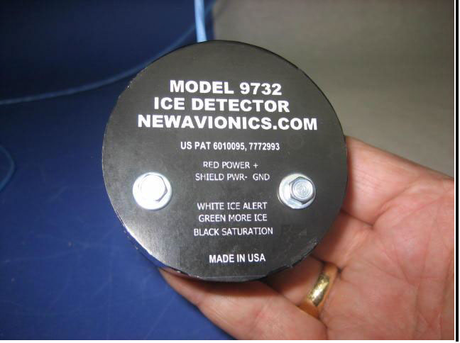
Figure 1 — Model 9732-STEEL aviation ice detector is a commercial, off-the-shelf , in-flight ice sensor that monitors the optical characteristics of whatever substance is in contact with the probe, either air (NO ICE) or water ice (ICE ALERT). Reports rate-of-ice-accumulation in three stages. Acrylic housing is size and shape of a hockey puck. * Probe is type 316-L marine grade stainless steel for subsonic flight. See fig 2.
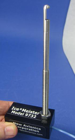
Ice*Meister™ Model 9732-STEEL detects ICE on any aircraft. It is demonstrably the smallest, lightest, most sensitive ice sensor aloft today. Model 9732 is entirely optical, has no MHz clock, no moving parts. See figure 2. When ice forms, it forms directly on the probe’s optical surfaces. Model 9732 is completely sealed and potted solid with 2-part epoxy; no exposed electronics.
NOTE: Photos subsequent to figure 2 may differ slightly from Model 9732-STEEL.
Because of its slender cross-sectional area, ice forms on probe earlier than on large-area airframe members, such as windshields, wing leading edges, tailplane leading edges, wheels, struts, etc.
The complete unitized system consists of a stainless steel ice sensor probe, a circuit board potted into the housing, and a lightweight blue cable that connects the sensor to the host system. Installation is accomplished by means of two #6-32 stainless steel screws through the body of the sensor, and the probe’s 5/16”-24 thread and hex nut. See figure 2 a, b.
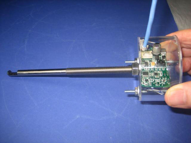
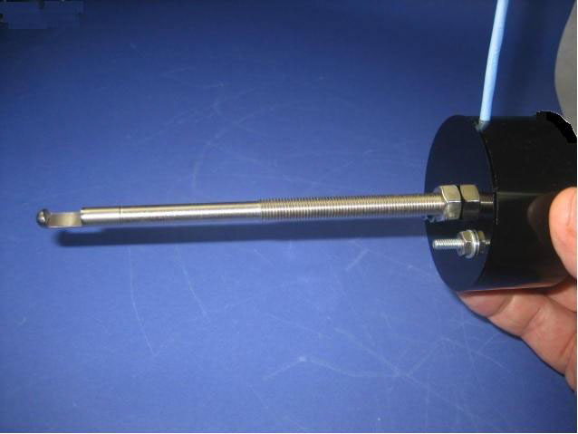
Figure 2 a, b — Model 9732 ice detector adds lightness to any aircraft. Employs compact, highly-integrated electronic circuits. Integrates optical probe with interface electronics into small, hockey-puck housing. Two-part epoxy-filled assembly is robust, solid as a brick, no moving parts, probe is robust type 316-L marine grade stainless steel.
PRINCIPLE OF OPERATION
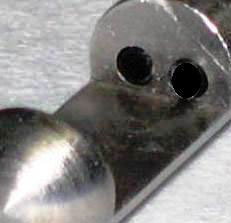
9732’s OPTICAL ICE-SENSING SYSTEM consists of two light-manipulating windows, an air gap facing the oncoming air stream, and a reflecting wall.
In-flight ice sensing occurs when molecules of ice appear on the surfaces of either optical window and/or on the reflecting wall of the air gap at the end of the probe. Accumulating molecules of ice kill reflectivity of the airgap wall, attenuate the signal, and trigger ICE ALERT.
The sensor monitors ambient air for the empirical presence of an icing domain, which by definition forms ice on an exposed surface.
The observed fact of physical ice formation and detection has been documented at NASA Glenn Icing Research Tunnel according to a matrix of temperature, humidity, altitude, air speed, liquid water content, drizzle drop diameter, and air pressure. Test tunnel matrix and report available upon request.
THE PROBE DOES NOT SENSE ICE. The probe is simply a structural member that fixes the optical ice sensing elements in alignment with each other, and provides a means of attachment to the aircraft.
Ice formations on an exposed surface in an icing domain can be either clear ice or rime ice, depending upon atmospheric variables. Ice*Meister™ detects clear ice by its optical index-of-refraction, and rime ice by its optical opacity, both simultaneously. If it is necessary for the pilot to differentiate between clear and rime ice formations on the airframe, 9732 reports that difference per “test technique II”.
IN NON-ICING CONDITIONS, the aircraft’s ambient wind stream removes liquid H2O from the probe.
Air is in contact with the probe. The probe senses air, and reports NO-ICE.
IN ICING CONDITIONS, H2O molecules bind together and accumulate on the optical surfaces as a solid, resisting removal by the ambient windstream. ICE is in contact with the probe. The probe senses ICE, and 9732 reports one or more of three icing conditions: ICE ALERT, MORE ICE, SATURATION.
See the red panel in the upper right corner of figure 4, below:
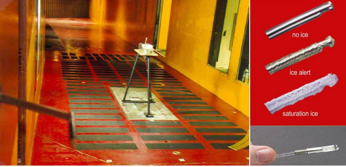
Figure 4 a, b, c — Test program conducted at NASA Glenn’s Icing Research Tunnel demonstrates Model 9732 conforms to defacto standard Minimum Operational Performance for In-flight Icing Detection Systems SAE AS 5498 5.2.1.1.1. See also SAE AIR 4367 4.11. Note Pitot tube in left foreground.
INSTALLATION
Model 9732 provides a 3-point installation system, with (1) 5/16-24 thread on the probe itself, and (2) #6-32 screws. Alignment is offset to damp mechanical resonance.
The sensor mounts inside and underneath the wing, with the air gap facing forward. This maximizes sensitivity, helps protect the probe from unwanted UV and IR radiation, and shelters the probe from precipitating dirt and other debris while the aircraft is parked on the tarmac.
Figure 5 — 9732 installs with (2) #6-32 screws through wing and directly through the epoxy-filled body of the unit. The steel probe’s 5/16-24 thread provides the third attachment screw.
LIGHTWEIGHT BLUE CABLE
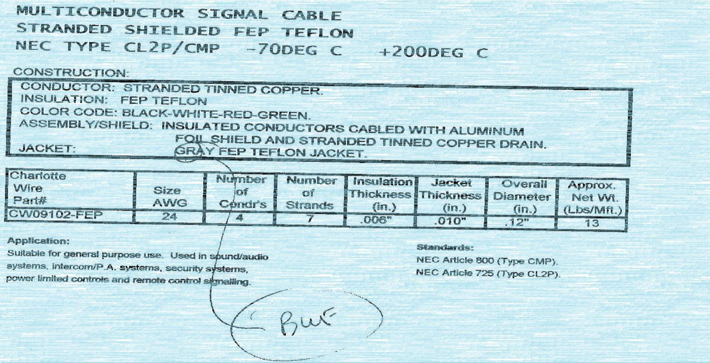
Figure 6 — Lightweight blue cable specifications.
Click here for full data sheet